A hybrid solar inverter must manage several jobs at once. It converts photovoltaic power, controls battery charging, supports grid interaction, and responds to changing household loads. At the center of these operations sits the Hybrid Inverter Pcb. It connects switching devices, sensors, control processors, protection circuits, and communication interfaces inside one compact platform.
Professor Frede Blaabjerg, a leading power-electronics researcher, has stated, “Power electronics is the key technology for future energy systems.” This principle explains the board’s importance. A carefully engineered Hybrid Inverter Pcb can reduce electrical losses, improve switching control, and help maintain stable output during fast changes in sunlight. Its copper traces carry high current. Its thermal paths guide heat away from power components. Small weaknesses can become large failures.
Reliability is not only about selecting premium components. Engineers must consider creepage distance, electromagnetic interference, moisture, vibration, and repeated thermal cycling. A board may perform perfectly in a cool laboratory, then struggle inside a hot outdoor enclosure. That gap deserves attention. It is easy to overstate PCB performance without discussing installation conditions, firmware quality, or maintenance practices.
This article examines why the Hybrid Inverter Pcb matters, how its main sections work, and which design choices influence safety, efficiency, and service life. The discussion also recognizes a practical limitation: no PCB operates alone. The inverter’s enclosure, software, cooling system, and installation quality can either protect the board or expose its weaknesses.
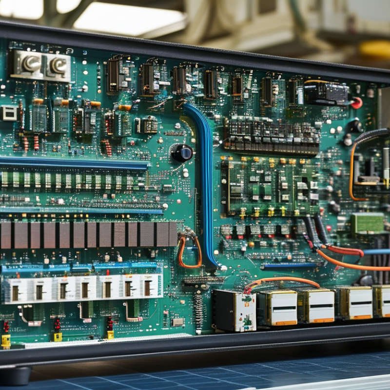
A hybrid inverter PCB is the electronic control board inside a hybrid solar inverter. It links the solar input, battery, household loads, and utility connection. Copper traces carry power signals, while smaller circuits measure voltage, current, temperature, and frequency. A microcontroller interprets these readings and directs switching devices with precise timing. This board is the inverter’s decision center. Not the whole inverter.
During daylight, the PCB can route solar energy to appliances, charge the battery, or limit output when generation changes. At night, it helps coordinate battery discharge and maintain stable power for connected equipment. Relays, isolation components, fuses, communication ports, and protection circuits support these tasks. In practical testing, a loose connector or heat-stressed solder joint can create intermittent faults that seem confusing. Good PCB design therefore requires controlled clearances, thermal management, noise reduction, and verified firmware. Small faults matter.
Reliability also depends on installation conditions. Dust, humidity, vibration, and repeated temperature swings can slowly weaken connections. A robust PCB uses suitable materials and monitors overvoltage, overcurrent, overheating, and isolation problems. Still, no circuit board is perfect. Sensor tolerances and software assumptions can cause unexpected behavior during rapid weather changes. Qualified testing, clear documentation, and serviceable layouts matter as much as rated power. Technicians should inspect fault records rather than replace parts blindly. This approach is less dramatic, but more dependable.
Why Is Hybrid Inverter PCB Important for Solar Inverters?
The hybrid inverter PCB controls how solar energy becomes usable electricity. It receives DC power from photovoltaic panels and sends precise switching signals to power semiconductors. These signals create a stable AC waveform for household loads or the utility connection. At the same time, the PCB manages battery charging and discharging. It constantly reads voltage, current, temperature, and frequency. These measurements help the controller adjust power flow within milliseconds. In practical systems, this control prevents unstable output when clouds pass over the panels.
A well-designed PCB also coordinates MPPT, which keeps the solar array near its most productive operating point. Sensors report changing conditions, while embedded software selects safer operating limits. Protection circuits can respond to overcurrent, short circuits, overheating, and abnormal grid conditions. Layout quality matters too. Short switching paths reduce electrical noise, and suitable spacing helps withstand high voltage. During testing, engineers often inspect thermal images and waveform measurements under changing loads. No design is perfect. A missed heat concentration can appear only after months of daily operation.
Tips: Keep the PCB enclosure dry and clean, and allow adequate airflow around the inverter. Check connection terminals during scheduled maintenance. Never ignore unusual buzzing, heat, or repeated fault messages. These details may reveal stress before a major failure. Also, confirm that replacement boards match the inverter’s voltage, battery, and communication requirements.
Why Is Hybrid Inverter PCB Important for Solar Inverters?
The hybrid inverter PCB coordinates power from solar panels, batteries, the grid, and household loads. It acts like a compact traffic controller. Power switches manage high-current energy conversion between DC and AC. Gate drivers turn these switches on and off with precise timing. Small timing errors can create heat, noise, or unstable output. Copper traces also need suitable width to prevent excessive voltage drop.
DC-link capacitors reduce voltage ripples near the switching stage. They store energy during brief load changes. Current sensors measure charging, discharging, and solar input levels. Voltage sensors monitor battery and DC bus conditions. Their readings help the controller limit overcurrent and prevent unsafe operating states. Relays or contactors separate the battery and grid circuits when faults occur. Isolation barriers protect low-voltage control electronics from dangerous power sections.
The control processor runs protection logic, charging profiles, and energy-priority settings. Communication circuits exchange data with displays, meters, and monitoring systems. Thermistors placed near switches and capacitors detect rising temperatures. In practical testing, engineers inspect solder joints, connector pressure, and thermal paths carefully. A clean schematic is not enough. A loose connector can still damage reliability. PCB layout must also respect creepage and clearance distances. These details are easy to overlook during a fast design review. Careful testing under cold starts, heavy loads, and battery changes exposes weaknesses before installation.
| PCB Section or Component | Primary Function | Role in a Hybrid Inverter | Typical Design Considerations | Why It Matters |
|---|---|---|---|---|
| Microcontroller and Control Logic | Executes control algorithms, monitors operating conditions, and coordinates switching events. | Manages solar generation, battery charging, grid interaction, and backup-load operation. | Fast processing, precise timing, isolated communication, watchdog protection, and reliable firmware operation. | Determines power-flow accuracy, system responsiveness, and overall operating stability. |
| DC-DC Converter Stage | Converts one DC voltage level to another while regulating current and voltage. | Performs maximum power point tracking and controls the energy exchanged with the battery. | High-efficiency switching topology, suitable inductors, low-loss semiconductors, and thermal management. | Improves energy harvesting from photovoltaic panels and supports efficient battery utilization. |
| Power Semiconductor Switches | Rapidly switch electrical current to create controlled DC or AC waveforms. | Enable DC conversion, DC-AC inversion, battery charging, and bidirectional energy flow. | Voltage and current ratings must include design margin; switching losses, heat dissipation, and layout inductance require attention. | Directly affects efficiency, output capacity, electromagnetic noise, and service life. |
| Gate-Driver Circuit | Provides the correct voltage, timing, and isolation needed to control power switches. | Synchronizes high-side and low-side switching devices in inverter and converter bridges. | Fast turn-on and turn-off, dead-time control, undervoltage lockout, and isolation where required. | Reduces cross-conduction risk and helps maintain safe, efficient switching. |
| DC-Link Capacitors | Stores short-term electrical energy and reduces DC-bus voltage ripple. | Provides a stable intermediate DC voltage between the input stages and the AC inverter bridge. | Capacitance, ripple-current rating, voltage rating, temperature capability, and lifetime must be matched to the design. | Supports waveform quality and protects switching devices from excessive bus fluctuations. |
| MPPT Measurement and Control Circuit | Measures photovoltaic voltage and current to identify the panel operating point that provides maximum power. | Adjusts the DC-DC converter so solar modules operate efficiently under changing sunlight and temperature conditions. | Accurate sensors, suitable sampling speed, filtering, and control algorithms are essential. | Can increase usable solar energy, especially during changing weather or partial shading. |
| Battery Interface and Protection | Controls battery charging and discharging while monitoring electrical limits. | Enables energy storage, backup power, peak-load support, and time-based energy management. | Must coordinate with the battery management system and include overcurrent, overvoltage, undervoltage, and temperature protections. | Improves battery safety, usable capacity, and expected service life. |
| AC Inverter Bridge and Output Filter | Converts DC power into synchronized AC power and reduces switching-frequency components. | Supplies household or backup loads and, where permitted, synchronizes with the utility grid. | Requires appropriate inductors, capacitors, switching frequency, harmonic control, and insulation clearances. | Influences output waveform quality, acoustic noise, electromagnetic compatibility, and load compatibility. |
| Voltage and Current Sensors | Measure electrical values for feedback, protection, and energy calculation. | Monitor PV input, battery current, DC-link voltage, AC output, and grid conditions. | Accuracy, bandwidth, isolation, temperature drift, and sensor placement must be considered. | Provides the data required for stable control and rapid fault detection. |
| Protection and Surge Suppression | Limits damage caused by overcurrent, short circuits, voltage surges, and abnormal operating conditions. | Protects DC inputs, battery connections, AC outputs, control circuits, and switching devices. | May include fuses, circuit breakers, transient protection devices, pre-charge circuits, and fault shutdown logic. | Reduces equipment damage and helps improve operational safety. |
| Isolation and Relay Control | Separates hazardous power circuits from low-voltage control circuits and controls connection paths. | Supports safe grid disconnection, backup-mode transfer, anti-islanding functions, and controlled start-up. | Requires appropriate creepage, clearance, insulation, relay contact ratings, and switching sequence control. | Helps protect users, connected equipment, and maintenance personnel. |
| Communication Interfaces | Exchanges operating data, commands, and status information with external devices. | Connects the inverter with battery management systems, meters, monitoring systems, and user interfaces. | Needs noise immunity, galvanic isolation where appropriate, reliable protocols, and secure fault handling. | Enables coordinated energy management, diagnostics, and remote monitoring. |
| Thermal Management and PCB Layout | Distributes heat and electrical current safely through copper planes, thermal paths, heat sinks, and airflow provisions. | Maintains component temperatures during continuous solar conversion, battery operation, and high-load backup events. | Requires suitable copper thickness, thermal vias, creepage and clearance, low-noise routing, and separation of power and signal paths. | Strongly affects efficiency, electromagnetic compatibility, reliability, and product lifetime. |
A hybrid inverter PCB connects solar panels, batteries, the grid, and household loads. Its design directly affects conversion efficiency and operating safety. Short current paths reduce copper losses and voltage drops. Carefully selected switching components also limit heat during power conversion.
Thermal management starts with the PCB layout. Engineers use wider copper areas, thermal vias, and separated hot zones to move heat away from sensitive circuits. Temperature sensors must sit near likely heat sources, not in convenient but inaccurate locations. Small details matter. Poor placement can trigger late protection responses.
Safety depends on more than insulation thickness. Correct creepage and clearance distances help prevent arcing between high-voltage sections. Isolation barriers should separate control signals from dangerous power paths. Protective circuits can detect overcurrent, overvoltage, ground faults, and abnormal temperatures. In field inspections, dust, humidity, and loose terminals often expose weaknesses that laboratory tests miss.
EMI control also influences reliability. A thoughtful ground strategy and carefully routed gate-drive signals can reduce unwanted interference. However, no layout is perfect. Designers may accept limited compromises because space, cost, and heat compete constantly. Those decisions require testing under changing sunlight, battery conditions, and load demand. A PCB that performs well at room temperature may behave differently inside a hot enclosure. Detailed validation remains essential.
A hybrid inverter PCB controls power flow between solar panels, batteries, household loads, and the grid. Its maintenance directly affects efficiency, safety, and service life. Before inspection, technicians should isolate every energy source and confirm zero voltage with calibrated instruments.
A battery may remain dangerous after shutdown.
Dust, humidity, heat, and vibration slowly damage PCB performance. Inspectors should check discolored solder joints, swollen capacitors, loose connectors, and corrosion near terminal blocks. Thermal imaging can reveal hot components before visible failure. Firmware logs may also expose repeated overcurrent or overheating events. Keep cooling paths clear. Small blockages matter.
Maintenance intervals should match local conditions, not a fixed calendar. Coastal systems need closer corrosion checks, while dusty sites require more frequent cleaning. Use approved methods and avoid aggressive solvents. A clean board can still hide insulation damage. No checklist is perfect. That deserves honest attention.
Future hybrid inverter PCBs will likely use denser layouts, stronger power semiconductors, and better sensor integration. Predictive maintenance could compare temperature trends, switching behavior, and capacitor aging. Modular designs may shorten repairs and reduce electronic waste. However, smarter monitoring creates new software and cybersecurity responsibilities. Engineers must balance compact design with heat dissipation and service access. Reliability should be tested under realistic temperature cycles, load changes, and battery conditions, rather than laboratory averages alone.


